Steel structure plant design process
The design of steel structure plant (including other steel structure buildings) needs to go through four stages: architectural drawing design, structural drawing design, processing detail drawing design and maintenance system drawing design. Each stage expresses different content and needs to use different design software. In this paper, according to the design process of a steel structure plant project, let us understand the design process of general steel structure buildings;
1, Architectural drawing design
This stage requires the use of “Tianzheng Architecture” software. This is a software specialized in architectural design. It establishes a three-dimensional model of a building in the form of a plan element (walls, columns, doors and Windows, floors, etc.), which can accurately reflect all the information that a building needs to express, such as the plane layout, functional division, location of doors and Windows, facade effect, etc.
The Tianzheng interface is as follows:
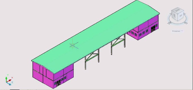
Tianzheng Building is an application program based on CAD software platform. The operation of CAD can be basically used in Tianzheng building, and Tianzheng building has many extended functions. For example, the basic elements of CAD are points, lines, faces, bodies, labels, etc.; The basic drawing elements of Tianzheng building are columns, walls, doors and Windows, stairs and other data groups containing three-dimensional information, styles, materials, etc. These data groups are combined to form the entire building database, based on this database, the entire building can be expressed in plan, elevation, section, solid renderings, doors and Windows information table and other plane drawings.
The layout of the first floor is as follows:

The first layer perspective is as follows:
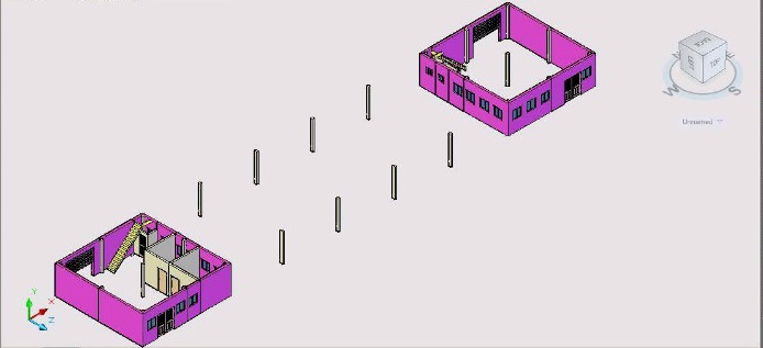
The second layer perspective is as follows:
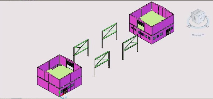
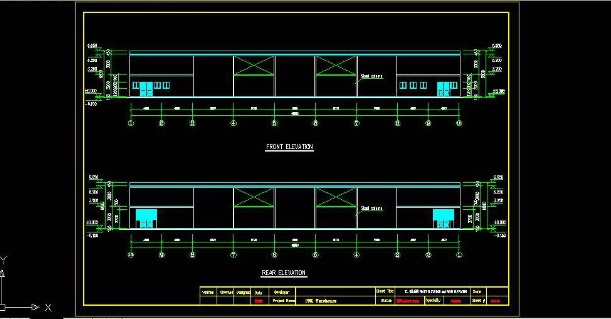
The elevation is as follows:
2, Design of structure diagram
This stage requires the use of “PKPM”, “3D3S”, “MIDAS”, “SAP2000”, “ETABS”, “ANSYS” and other structural calculation software for structural analysis and calculation, to determine the section size of the component, node connection parameters, and then use CAD to draw. This stage also requires the design of concrete foundations, concrete floors and other related structures.
Taking PKPM, the most widely used structural analysis software in China, as an example, the process of steel structure calculation is explained.
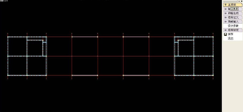
The PKPM screen is as follows:

Generally, the basic information required for structural analysis such as shaft network, column, beam, support, load and load transfer mode is first established in STS or PMCAD module, and then calculated and analyzed in a module such as SATWE-8, SATWE, TAT, etc. Finally, the calculated parameters (including stress ratio, displacement value, deflection, natural vibration period, etc.) are checked. Make it meet the specification requirements. If a certain item does not meet the requirements of the specification, it is necessary to repeatedly adjust the section size of the component, the connection mode, etc., so that the relevant parameters of the calculation result all meet the requirements of the specification. PKPM can also be directly exported to meet the requirements of the domestic specification.
The SATWE-8 interface is as follows:
SATWE-8 member deflection display
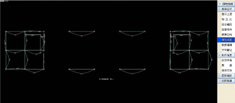
Structural design is the unity of safety, economy, beauty, easy construction and other elements, and is one of the most important links related to the safety of the whole building.
3, processing detail design
At this stage, “***” software is mainly used, and some designers still use CAD for detailed design.
*** Software interface as follows:
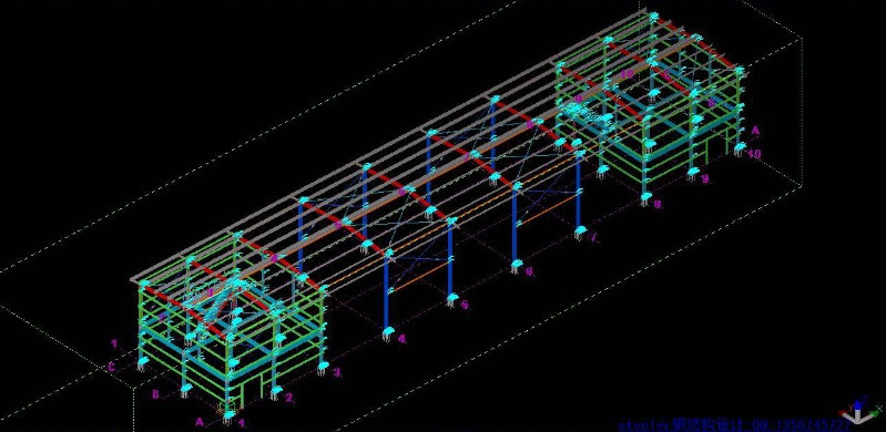
Steel structure is different from concrete, masonry and other structural forms, processing detail design is also a very important link. Because the raw materials of the steel structure processing plant are steel plates and sections of specific sections, the processing of raw materials into beams, columns and other components that can be directly installed on the construction site needs to go through the steps of steel plate (section steel) cutting, cutting, drilling, welding, and other steps, while it also needs to remove rust, painting and other subsequent processes. The processing detail drawing divides the beam, column and other components into a single steel plate (section steel) parts, indicating the cutting, cutting and punching sizes of all parts, and indicating how the parts are assembled into a beam and column component. The detailed layout also shows how the various beam and column members are assembled into a complete building structure.
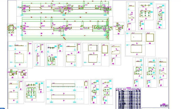
XSTEEL component drawings are as follows:
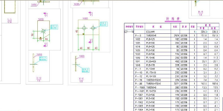
*** is a 3D intelligent steel structure detail drawing software. In this virtual space, a complete steel structure model is built, which not only includes the geometric size of the joint parts, but also all the information including material specifications, cross sections, node types, materials, user comments, etc. Based on this virtual space model, it is easy to create a variety of drawings for factory processing and on-site installation, such as component drawings, part drawings, component layout drawings, and material bills.
Part drawings and material representations are as follows:
4, maintenance system diagram design
This part mainly uses “CAD” software.
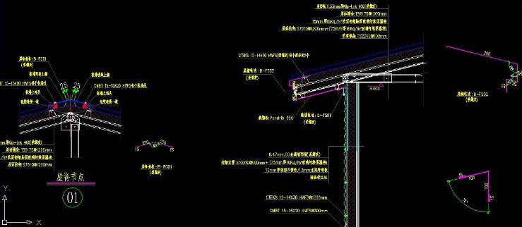
The maintenance system mainly refers to the design of the roof, wall, cornice, ceiling, etc., in addition to the structure and decoration. The focus of this part is on the details, to ensure that the building is waterproof, thermal insulation, thermal insulation, and beautiful. This part of the design mainly includes: roof panel, wall panel, thermal insulation cotton selection, ridge, cornice, gable, door and window openings, outer corner, bottom of the outer wall and other positions of the edge approach. Part of the maintenance design needs to be communicated and confirmed with the owner and architect repeatedly.
The maintenance node diagram is as follows:
5, Summary
Architectural drawing, structural drawing, processing detail drawing, maintenance system drawing are all aspects of the design drawings, the emphasis of the expression of information is different. The main goal of the architectural drawing is to meet the client’s requirements for the function, appearance, layout, space, etc.
The main goal of the structure drawing is to meet the requirements of safety, economy and easy construction of the entire building.
The main objective of machining detail drawing is to meet the processability requirements of structural members.
The main goal of maintenance system drawing is to meet the requirements of building comfort, beauty and economy.
The order of drawing of each stage is also different. Generally, the architectural drawing is designed according to the functional requirements of the owner first. Then, according to the position of axis network, elevation, wall, column and plate in the building drawing, the structure arrangement is determined, the structure calculation is carried out, and the steel structure drawing is drawn. Next, draw the processing details according to the structural drawings, and the factory processes according to the details; Finally, draw maintenance system drawings according to building drawings and reference structure drawings.
Friends who need to do steel structure design such as plant, frame and grid can contact me.

 中文
中文 English