Business Scope
Steeler provides integrated steel structure design, manufacturing and construction services.
 High-tech enterprise
Steel structure design
High-tech enterprise
Steel structure design


177-1762-1528
InquiryThe design of steel structure workshop needs to go through the architectural drawing design, structural drawing design, processing detail drawing design, maintenance system drawing design of a total of four stages, the content of each stage is different, need to use different design software;In this paper, according to the design process of a steel structure workshop project, let you understand the design process of general steel structure building;
1. Architectural drawing design
This stage requires the use of tianzheng Architecture software.This is a special software for architectural design, it is in the form of floor plan elements (walls, columns, doors and Windows, floors, etc.), to establish a three-dimensional model of the building, can accurately reflect the layout of the building, functional division, the location of doors and Windows, facade effect and other architectural need to express all the information;
Tianzheng interface is as follows:

Tianzheng architecture is an application program based on CAD software platform.CAD operation can be used in tianzheng building, and tianzheng building has many extended functions.For example: the basic elements of CAD are points, lines, surfaces, bodies, notes and so on;Tarch is the basic graph element of columns, walls, doors and Windows, stairs and other contains the three-dimensional information, style, material, such as data set, the data set together make up the whole building database, on the basis of this database can be the whole building with floor plan, elevation, section, entity rendering, door to express information table, and other forms of graphic drawing.
The floor plan of the first floor is as follows:

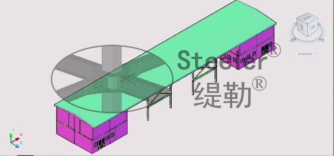
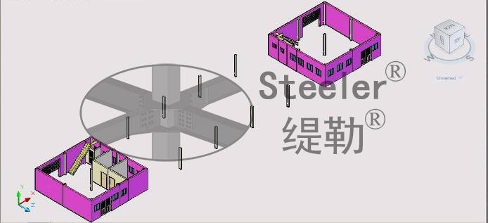
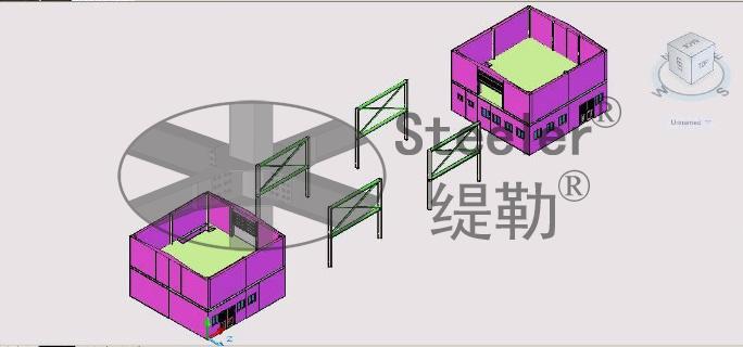
The perspective of the first floor is as follows:

The perspective of the second floor is as follows:

The elevation is as follows:

2. Structure drawing design
At this stage, one or more structural calculation software such as "PKPM", "YJK ", 3D3S ", "MIDAS", "SAP2000", "ETABS" and "ANSYS" should be used to analyze and calculate the structure, determine the section size of the component and the connection parameters of the node, and then draw the drawing with CAD.This stage also needs to carry out concrete foundation, concrete floor and other related structure design.
The most widely used structural analysis software PKPM is taken as an example to illustrate the calculation process of steel structure.
The PKPM interface is as follows:

In general, the basic information needed for structural analysis such as shaft network, column, beam, support, load and load transfer mode is first constructed in STS or PMCAD module, and then the calculation and analysis are carried out in a module such as SATWE-8, SATWE and TAT. Finally, the parameters of the calculation results (including stress ratio, displacement value, deflection, natural vibration period, etc.) are checked.Make it meet the specification requirements.If something does not meet the requirements of the code, it is necessary to repeatedly adjust the section size of the component, connection mode, etc., so that the calculation of relevant parameters all meet the requirements of the code.PKPM can also directly export calculations that meet the requirements of domestic specifications.
The interface of SATWE-8 is as follows:


The deflection of SATWE-8 component is shown as follows:

Structural design is the unity of safety, economy, beauty, easy construction and other elements, is one of the most important links related to the safety of the whole building.
3. processing detail design
In this stage, detailed design software is mainly used, and some designers still use CAD to do detailed design.
The detailed software interface is as follows:

Steel structure is different from concrete, masonry and other structural forms, processing detail design is also an important link.Because the raw material of steel structure processing plant is steel plate and specific section of steel, the raw material processing into construction site can be directly installed beam, column and other components, need to go through steel plate (steel) blanking, cutting, drilling, welding and other steps, but also need to rust, paint and other subsequent processes.The detailed processing drawing divides the beam, column and other components into single steel (section) parts, indicating the cutting, cutting and punching dimensions of all the parts, and showing how the parts are assembled into individual beam and column components.The detailed layout also shows how the various beams and columns are assembled into a complete structure.
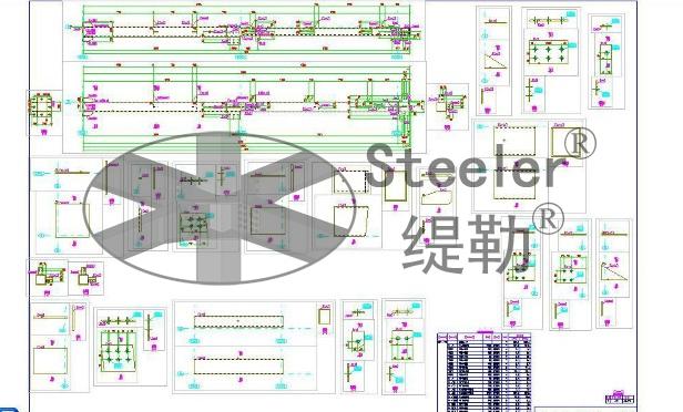
The drawings are as follows:

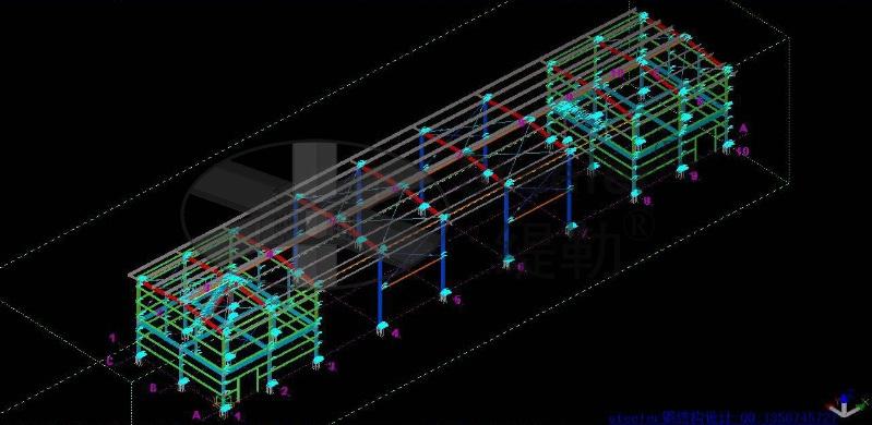
Detail drawing software is a 3d intelligent detail drawing software for steel structure.A complete steel structure model is built in this virtual space. The model includes not only the geometric size of the components, but also all the information such as material specifications, cross sections, node types, materials, user comments, etc.Based on this virtual spatial model, it is easy to create component drawings, part drawings, component layout drawings, bill of materials and other drawings needed for factory processing and field installation.
Part drawing and material representation are as follows:

4. Design of maintenance system diagram
This part mainly uses "CAD" software.
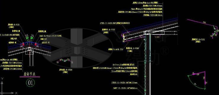
Maintenance system mainly refers to the roof, wall, cornice, ceiling and other structures and decoration in addition to the design.This part of the focus on the details of the treatment, to ensure that the building waterproof, heat preservation, heat insulation, beautiful.This part of the design mainly includes: roof panels, wall panels, selection of thermal insulation foam, ridge, cornice, gable, door and window openings, external corners, wall bottom and other positions of the edge approach.Part of the maintenance design needs to be communicated and confirmed with the owner and architect repeatedly.
The following figure shows the maintenance node:

5, Summary
Building drawing, structure drawing, processing detail drawing and maintenance system drawing are all aspects of the design drawings, which express information with different emphasis.The main objective of the building drawing is to meet the client's requirements for the building's function, appearance, layout, space, etc.
The main goal of structure drawing is to meet the safety, economy and easy construction requirements of the whole building.
The main objective of machining detail drawing is to meet the machinability requirements of structural members.
The main goal of the maintenance system diagram is to meet the requirements of building comfort, aesthetics and economy.
Each stage of the drawing of the drawing order is different, generally in accordance with the functional requirements of the owner first design building drawings;Then according to the building drawing shaft network, elevation, wall, column, plate position to determine the structure layout, structural calculation, drawing steel structure;Next, according to the structural drawing drawing processing detail, the factory processing according to the detail drawing;Finally, according to the building drawing, reference structure drawing, drawing the maintenance system drawings.
If you need to do workshop, frame, grid and other steel structure design friends,you can contact us.
Add:Xufu Road, Jinshan District, Shanghai
Mobile:177-1762-1528
Website:www.steeler.cn
E-mail:steeler@steeler.cn

